
A lo largo del documento vamos a tratar de controlar una carga en DC mediante rampas de subida y bajada, y valores fijos de Potencia (MOSFET), una carga en AC mediante rampas de subida y bajada, y valores fijos de Potencia (TRIAC), y tambien veremos el funcionamiento de un RELE con una carga de AC, y todo ello controlado con un ATMEGA328P en configuracion de "Arduino Uno, personalizado".
Throughout the paper we will try to control a load in DC via ramps up and down , and fixed values of Power (MOSFET ) , a load on AC via ramps up and down , and fixed values of power ( TRIAC ) and also see the operation of a RELAY with a load of AC, and all controlled with ATMEGA328P in settings "Arduino Uno, personalized ".
--== CONTROL DE UNA CARGA DE DC ==--
-= Español =-
Empecemos con el control de una carga en DC, previamente hemos realizado un GANTT y un PERT, para poder organizarnos y no perder de vista lo que estamos realizando.
-= English =-
Let's start with the control of a load in DC , we have previously done a GANTT and PERT , to organize and keep track of what we are doing.
-= GANTT =-

-= PERT =-

-= Español =-
Una vez tenemos claro las tareas que debemos realizar, empecemos por el diseño del circuito, utilizaremos el programa "PROTEUS" con su herramienta "ISIS", para realizar el esquema del circuito que va a controlar una carga en DC.
-= English =-
Once we are clear about the tasks we perform , let's start circuit design , use the "PROTEUS" program with its "ISIS" tool for the circuit diagram that will handle a load in DC .
-= English =-
Once we are clear about the tasks we perform , let's start circuit design , use the "PROTEUS" program with its "ISIS" tool for the circuit diagram that will handle a load in DC .

-= Español =-
Ahora una vez terminado el esquema, usaremos la herramienta "ARES" del programa "PROTEUS", para realizar la PCB del circuito y poder fabricarla fisicamente.
-= English =-
Now once finished scheme , we will use the "ARES" tool "PROTEUS" program , for the PCB and to fabricate circuit physically .
-= English =-
Now once finished scheme , we will use the "ARES" tool "PROTEUS" program , for the PCB and to fabricate circuit physically .

-= Español =-
* NOTA: Fijarse solo en la parte iluminada, puesto que es la placa repetida 3 veces, es para otro proyecto, pero tiene el mismo funcionamiento.
-= English =-
* NOTE : Pay attention only in the illuminated part , since it is repeated 3 times plate is for another project , but has the same performance .
-= Español =-
Lista de materiales con sus "DATASHEET" correspondientes pinchando en su nombre.
-= English =-
List of materials with their "DATASHEET" corresponding clicking on its name.
-= English =-
* NOTE : Pay attention only in the illuminated part , since it is repeated 3 times plate is for another project , but has the same performance .
-= Español =-
Lista de materiales con sus "DATASHEET" correspondientes pinchando en su nombre.
-= English =-
List of materials with their "DATASHEET" corresponding clicking on its name.
- IRF540

- 4N25

- 1N4001

- RES 680R

- RES 10k

-= Español =-
Continuamos con el control de una carga en AC, previamente hemos realizado un GANTT y un PERT, para no perder la costumbre.
-= English =-
We continue to control a load in AC , we have previously done a GANTT and PERT , not to lose the habit .
- 4N25
- 1N4001
- RES 680R
- RES 10k
--== CONTROL DE UNA CARGA DE AC ==--
-= Español =-
Continuamos con el control de una carga en AC, previamente hemos realizado un GANTT y un PERT, para no perder la costumbre.
-= English =-
We continue to control a load in AC , we have previously done a GANTT and PERT , not to lose the habit .
-= GANTT =-

-= PERT =-

-= Español =-
Despues del "GANTT" y el "PERT", volvemos a utilizar el programa "PROTEUS" con su herramienta "ISIS", para realizar el esquema del circuito que va a controlar una carga en AC, aqui hay una diferencia, puesto que para el control de una carga de AC, vamos a usar dos circuitos independientes, por lo tanto uno de ellos realizara el control de la carga propiamente dicho ( TRIAC ), y el otro circuito se encargara de detectar el paso por cero de una onda senoidal rectificada por un puente de diodos ( ZERO ), y luego alimentaremos ambos circuitos con la misma Fase y Neutro.
-= English =-
After the "GANTT" and "PERT" , we again use the " Proteus " program with its "ISIS" tool for the circuit diagram that will handle a load on AC , here there is a difference , since for control of a load of AC , we will use two separate circuits, so one of them perform the load control itself ( TRIAC ) , and the other circuit would be responsible for detecting the zero crossing of a sine wave rectified by a diode bridge ( ZERO ) , and then feed them both circuits with the same phase and Neutral .
-= TRIAC =-

-= Español =-
Terminado el esquema del circuito, pasamos a la herramienta "ARES" del "PROTEUS", para realizar la PCB del circuito.
-= English =-
Finished the circuit diagram , we turn to the "ARES" tool "PROTEUS" to make the PCB circuit .-= English =-

-= Español =-
Lista de materiales para el circuito del "TRIAC".
-= English =-
List of materials for the circuit "TRIAC" .
- MOC3021

- BT139

- RES 120R

- RES 330R

- FUSIBLE 3A

- CONDENSADOR 1n

- LED ROJO

-= Español =-
Ahora vamos con la otra parte del circuito, el detector de paso por cero, el cual nos permitira enviarle una señal al ATMEGA328P para que pueda controlar la carga de AC mediante el circuito del TRIAC.
-= English =-
Now for the other side of the circuit, the zero crossing detector , which will allow us to send a signal to ATMEGA328P so you can control the AC load by TRIAC circuit .-= English =-
-= ZERO =-

-= Español =-
Terminado el esquema del circuito, pasamos a la herramienta "ARES" del "PROTEUS", para realizar la PCB del circuito.
-= English =-
Finished the circuit diagram , we turn to the "ARES" tool "PROTEUS" to make the PCB circuit .-= English =-

-= Español =-
Lista de materiales para el circuito de "ZERO".
-= English =-
List of materials for the circuit "ZERO".
- 4N25
- BC250C

- RES 10k
- RES 33k 1w

-= Español =-
Ahora vamos a pasar a ver el circuito de un Relé para controlar una carga de AC, aqui pongo el esquema realizado en "ISIS".
-= English =-
Now let's go to see the circuit of a relay to control an AC load , here I put the scheme made in "ISIS" .

-= Español =-
A continuacion pasamos el esquema de "ISIS" a PCB mediante la herramienta "ARES" de "PROTEUS".
-= English =-
Below we outline of "ISIS" a PCB using the "ARES" tool "PROTEUS".-= English =-

-= Español =-
Lista de materiales para el circuito de "RELE".
-= English =-
List of materials for the circuit "RELAY" .
- 4N25
- PN2222A

- RELE 12v DC 230 VAC

- 1N4007
- RES 680R
- RES 1k

-= Español =-
Una vez acabados todos los circuitos, pasamos al "cerebro" que los va a controlar a todos, un circuito basado en "ARDUINO" de manera personalizada usando el chip ATMEGA328P.
-= English =-
Once finished all circuits , we turn to "brain" that will control everyone , based on "ARDUINO" personalized circuit using the ATMEGA328P chip.
-= GANTT =-

-= PERT =-

Como podemos ver en el esquema realizado en "ISIS", hay modulos del "ARDUINO" que no estan, y otros que he añadido para este proyecto.
-= English =-
As we can see in the diagram made in "ISIS" , there are modules of "ARDUINO" that are not , and others who have added to this project.

-= Español =-
En la foto de la PCB, se aprecia que el PIN 1 del TTL deberia ir conectado al PIN 21 del ATMEGA328, eso se debe a que "PROTEUS" oculta los pines de VCC y GND en el "ISIS" y al pasarlo al "ARES" los marca en gris o ausentes.
-= English =-
In the photo on the PCB , shows that the PIN 1 of the TTL should be connected to PIN 21 of ATMEGA328 , that is because "PROTEUS" hidden pins VCC and GND in the "ISIS" and pass it to "ARES" marks in gray or absent.

-= Español =-
Lista de materiales para el circuito de "ARDUINO PERSONALIZADO".
-= English =-
List of materials for the circuit "ARDUINO CHAINS".
- ATMEGA328P

- Cristal 16MHz

- RES 1M

- RES 10k
- RES 220R

- CONDENSADOR 100n

-CONDENSADOR 22p

- PULSADOR

- LED ROJO
-= CODIGO DEL PROGRAMA =-
// --== INICIO INPORTACION DE LIBRERIAS ==--
#include <SoftwareSerial.h> // Librería que permite establecer comunicación serie en otros pins
// --== FIN INPORTACION DE LIBRERIAS ==--
// --== INICIO DECLARACION VARIABLES ==--
int AC_LOAD = 3; // PIN DEL TRIAC
int dimming = 128; // 0 = ON 128 = OFF
int Rele = 10; // PIN DEL RELE
int pwm= 9; // PIN DEL PWM
// --== FIN DECLARACION VARIABLES ==--
// --== INICIO DE CONFIGURACION ==--
void setup(){
pinMode(pwm, OUTPUT);
pinMode(Rele, OUTPUT);
pinMode(AC_LOAD, OUTPUT);// Set AC Load pin as output
digitalWrite(Rele, HIGH);
SoftwareSerial BT(8,7); //10 RX, 11 TX.
BT.begin(9600);
// --== INICIO CONFIGURACION TIMERS ==--
TCCR2B = (TCCR2B & 0xF8) | 4; // Configuramos el << TIMER 2 >> PIN 3 y 11 Afecta al Motor Avance y Motor Retroceso
// Frecuencias(Hz): =>1 = 31372.55 || =>2 = 3921.16 || =>3 = 980.39 || =>4 = 490.20 (Default) || =>5 = 245.10 || =>6 = 122.55 || =>7 = 30.64
TCCR1B = (TCCR1B & 0xF8) | 2; // Configuramos el << TIMER 1 >> PIN 9 y 10 Afecta al Motor Giro Izquierda y Motor Giro Derecha
// Frecuencias(Hz): =>1 = 31372.55 || =>2 = 3921.16 || =>3 = 490.20 (Default) || =>4 = 122.55 || =>5 = 30.64
//TCCR0B = (TCCR0B & 0xF8) | 2; // Configuramos el << TIMER 0 >> PIN 5 y 6 Afecta al Delay del Arduino (( NO TOCAR ))
// Frecuencias(Hz): =>1 = 62500 || =>2 = 7812.5 || =>3 = 976.5625 (Default) || =>4 = 244.140625 || =>5 = 61.03515625
// --== FIN CONFIGURACION TIMERS ==--
}
// --== FIN DE CONFIGURACION ==--
// --== INICIO DE FUNCIONES ==--
void zero_crosss_int(){
int dimtime = (75*dimming); // Para 50Hz => 75
delayMicroseconds(dimtime); // Cambio de Ciclo
digitalWrite(AC_LOAD, HIGH); // Activacion del Triac
delayMicroseconds(10); // Retraso del Triac
digitalWrite(AC_LOAD, LOW); // Desactivacion del Triac
// Funcion que configura el PIN 2 para el paso por Zero
// Calculo del Angulo : Periodo a 50Hz = 1/50 = 20ms
// Cada paso por Zero: (50Hz) -> 10ms ( 1/2 Periodo)
// 10ms = 10000us
// (10000us - 10us) / 128 = 75 (Approx)
}
// --== FIN DE FUNCIONES ==--
// --== INICIO DEL PROGRAMA ==--
void loop(){
// Comprobamos si el medio esta disponible
if ( BT.available() ){
// Guardamos lo que leemos del medio en una variable
int value = BT.read();
// Para cada valor de esa variable realizamos una accion concreta
// --== INICIO DEL CONTROL DC ==--
if ( value == '1' ){
// En el caso de recivir un '1' por el medio, realizamos un bucle para incrementar el valor del pwm, para realizar una rampa de subida lenta.
for ( int x=0; x<=255; x++){
analogWrite(pwm, x);
delay(120);
}
// Terminada la rampa, desactivamos el pwm.
analogWrite(pwm, 0);
}
if ( value == '2' ){
// En el caso de recivir un '2' por el medio, realizamos un bucle para incrementar el valor del pwm, para realizar una rampa de subida rapida.
for ( int x=0; x<255; x++){
analogWrite(pwm, x);
delay(40);
}
analogWrite(pwm, 0);
}
if ( value == '3' ){
// En el caso de recivir un '3' por el medio, realizamos un bucle para incrementar el valor del pwm, para realizar una rampa de bajada lenta.
for ( int x=255; x>0; x--){
analogWrite(pwm, x);
delay(120);
}
analogWrite(pwm, 0);
}
if ( value == '4' ){
// En el caso de recivir un '4' por el medio, realizamos un bucle para incrementar el valor del pwm, para realizar una rampa de bajada rapida.
for ( int x=255; x>0; x--){
analogWrite(pwm, x);
delay(40);
}
analogWrite(pwm, 0);
}
if ( value == '5' ){
// En el caso de recivir un '5' por el medio, establecemos el pwm en 64, que corresponde a un 25% de la potencia.
analogWrite(pwm, 64);
}
if ( value == '6' ){
// En el caso de recivir un '6' por el medio, establecemos el pwm en 127, que corresponde a un 50% de la potencia.
analogWrite(pwm, 127);
}
if ( value == '7' ){
// En el caso de recivir un '7' por el medio, establecemos el pwm en 191, que corresponde a un 75% de la potencia.
analogWrite(pwm, 191);
}
if ( value == '8' ){
// En el caso de recivir un '8' por el medio, establecemos el pwm en 64, que corresponde a un 100% de la potencia.
analogWrite(pwm, 254);
}
// --== FIN DEL CONTROL DC ==--
// --== INICIO DEL CONTROL RELE ==--
if ( value == '9' ){
// En el caso de recivir un '9' por el medio, activamos el rele.
digitalWrite(Rele, HIGH);
}
if ( value == 'a' ){
// En el caso de recivir una 'a' por el medio, desactivamos el rele.
digitalWrite(Rele, LOW);
}
// --== FIN DEL CONTROL DC ==--
// --== INICIO DEL CONTROL AC ==--
if ( value == 'b' ){
// En el caso de recivir una 'b' por el medio, activamos el PIN 2 del arduino, llamando ala funcion para configurarlo y usarlo.
attachInterrupt(0, zero_crosss_int, RISING);
delay(500);
// Realizamos un for para hacer una rampa de subida lenta.
for (int i=100; i >= 15; i--){
dimming=i;
delay(240);
}
// Desabilitamos el PIN 2 del arduino.
detachInterrupt(0);
}
if ( value == 'c' ){
// En el caso de recivir una 'c' por el medio, activamos el PIN 2 del arduino, llamando ala funcion para configurarlo y usarlo.
attachInterrupt(0, zero_crosss_int, RISING);
delay(500);
// Realizamos un for para hacer una rampa de subida rapida.
for (int i=100; i >= 15; i--){
dimming=i;
delay(80);
}
detachInterrupt(0);
}
if ( value == 'd' ){
// En el caso de recivir una 'd' por el medio, activamos el PIN 2 del arduino, llamando ala funcion para configurarlo y usarlo.
attachInterrupt(0, zero_crosss_int, RISING);
delay(500);
// Realizamos un for para hacer una rampa de bajada lenta.
for (int i=15; i < 100; i++){
dimming=i;
delay(240);
}
detachInterrupt(0);
}
if ( value == 'e' ){
// En el caso de recivir una 'e' por el medio, activamos el PIN 2 del arduino, llamando ala funcion para configurarlo y usarlo.
attachInterrupt(0, zero_crosss_int, RISING);
delay(500);
// Realizamos un for para hacer una rampa de bajada rapida.
for (int i=15; i < 100; i++){
dimming=i;
delay(80);
}
detachInterrupt(0);
}
if ( value == 'f' ){
// En el caso de recivir una 'f' por el medio, activamos el PIN 2 del arduino, llamando ala funcion para configurarlo y usarlo.
attachInterrupt(0, zero_crosss_int, RISING);
delay(500);
// Establecemos el valor fijo de 75 en la variable "dimming", el cual corresponde con un 25% de potencia.
dimming=75;
}
if ( value == 'g' ){
// En el caso de recivir una 'g' por el medio, activamos el PIN 2 del arduino, llamando ala funcion para configurarlo y usarlo.
attachInterrupt(0, zero_crosss_int, RISING);
delay(500);
// Establecemos el valor fijo de 55 en la variable "dimming", el cual corresponde con un 50% de potencia.
dimming=55;
}
if ( value == 'h' ){
// En el caso de recivir una 'h' por el medio, activamos el PIN 2 del arduino, llamando ala funcion para configurarlo y usarlo.
attachInterrupt(0, zero_crosss_int, RISING);
delay(500);
// Establecemos el valor fijo de 35 en la variable "dimming", el cual corresponde con un 75% de potencia.
dimming=35;
}
if ( value == 'i' ){
// En el caso de recivir una 'i' por el medio, activamos el PIN 2 del arduino, llamando ala funcion para configurarlo y usarlo.
attachInterrupt(0, zero_crosss_int, RISING);
delay(500);
// Establecemos el valor fijo de 15 en la variable "dimming", el cual corresponde con un 100% de potencia.
dimming=15;
}
if ( value == '0' ){
// En el caso de recivir un '0' por el medio, Desactivamos el PWM, el RELE y el PIN 2 del arduino.
analogWrite(xpwmx, 0);
digitalWrite(Rele, LOW);
detachInterrupt(0);
}
}
}
// --== FIN DEL PROGRAMA ==--
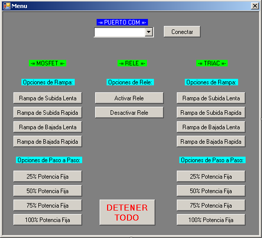
-= CODIGO DE LA APLICACION =-
Imports System.IO
Imports System.IO.Ports
Imports System.Threading
Imports System.ComponentModel
Public Class MainMenu
Dim myPort As Array
Dim myCom As String
Delegate Sub SetTextCallback(ByVal [text] As String)
Private Sub MainMenu_Load(sender As Object, e As EventArgs) Handles MyBase.Load
myPort = IO.Ports.SerialPort.GetPortNames()
ComboBox1.Items.AddRange(myPort)
Button1.Enabled = False
End Sub
Private Sub Label1_Click(sender As Object, e As EventArgs) Handles Label1.Click
End Sub
Private Sub Label3_Click(sender As Object, e As EventArgs) Handles Label3.Click
End Sub
Private Sub Label5_Click(sender As Object, e As EventArgs) Handles Label5.Click
End Sub
Private Sub Label4_Click(sender As Object, e As EventArgs) Handles Label4.Click
End Sub
Private Sub Button1_Click(sender As Object, e As EventArgs) Handles Button1.Click
SerialPort1.Write("1")
Dim sPath As String
Dim mySound As Media.SoundPlayer
sPath = "C:\mrsl.wav"
mySound = New Media.SoundPlayer(sPath)
mySound.Play()
End Sub
Private Sub Label9_Click(sender As Object, e As EventArgs) Handles Label9.Click
End Sub
Private Sub Button2_Click(sender As Object, e As EventArgs) Handles Button2.Click
SerialPort1.Write("2")
Dim sPath As String
Dim mySound As Media.SoundPlayer
sPath = "C:\mrsr.wav"
mySound = New Media.SoundPlayer(sPath)
mySound.Play()
End Sub
Private Sub Button3_Click(sender As Object, e As EventArgs) Handles Button3.Click
SerialPort1.Write("3")
Dim sPath As String
Dim mySound As Media.SoundPlayer
sPath = "C:\mrbl.wav"
mySound = New Media.SoundPlayer(sPath)
mySound.Play()
End Sub
Private Sub Button4_Click(sender As Object, e As EventArgs) Handles Button4.Click
SerialPort1.Write("4")
Dim sPath As String
Dim mySound As Media.SoundPlayer
sPath = "C:\mrbr.wav"
mySound = New Media.SoundPlayer(sPath)
mySound.Play()
End Sub
Private Sub Button19_Click(sender As Object, e As EventArgs) Handles Button19.Click
SerialPort1.Write("0")
Dim sPath As String
Dim mySound As Media.SoundPlayer
sPath = "C:\stop.wav"
mySound = New Media.SoundPlayer(sPath)
mySound.Play()
End Sub
Private Sub Button5_Click(sender As Object, e As EventArgs) Handles Button5.Click
SerialPort1.Write("5")
Dim sPath As String
Dim mySound As Media.SoundPlayer
sPath = "C:\m25.wav"
mySound = New Media.SoundPlayer(sPath)
mySound.Play()
End Sub
Private Sub Button6_Click(sender As Object, e As EventArgs) Handles Button6.Click
SerialPort1.Write("6")
Dim sPath As String
Dim mySound As Media.SoundPlayer
sPath = "C:\m50.wav"
mySound = New Media.SoundPlayer(sPath)
mySound.Play()
End Sub
Private Sub Button7_Click(sender As Object, e As EventArgs) Handles Button7.Click
SerialPort1.Write("7")
Dim sPath As String
Dim mySound As Media.SoundPlayer
sPath = "C:\m75.wav"
mySound = New Media.SoundPlayer(sPath)
mySound.Play()
End Sub
Private Sub Button8_Click(sender As Object, e As EventArgs) Handles Button8.Click
SerialPort1.Write("8")
Dim sPath As String
Dim mySound As Media.SoundPlayer
sPath = "C:\m100.wav"
mySound = New Media.SoundPlayer(sPath)
mySound.Play()
End Sub
Private Sub Button20_Click(sender As Object, e As EventArgs) Handles Button20.Click
SerialPort1.PortName = ComboBox1.SelectedItem()
SerialPort1.BaudRate = 9600
SerialPort1.DataBits = 8
SerialPort1.Parity = Parity.None
SerialPort1.StopBits = StopBits.One
SerialPort1.Handshake = Handshake.None
SerialPort1.Encoding = System.Text.Encoding.Default 'very important!
SerialPort1.Open()
Button1.Enabled = True
End Sub
Private Sub Button18_Click(sender As Object, e As EventArgs) Handles Button18.Click
SerialPort1.Write("9")
Dim sPath As String
Dim mySound As Media.SoundPlayer
sPath = "C:\ron.wav"
mySound = New Media.SoundPlayer(sPath)
mySound.Play()
End Sub
Private Sub Button17_Click(sender As Object, e As EventArgs) Handles Button17.Click
SerialPort1.Write("a")
Dim sPath As String
Dim mySound As Media.SoundPlayer
sPath = "C:\roff.wav"
mySound = New Media.SoundPlayer(sPath)
mySound.Play()
End Sub
Private Sub Button16_Click(sender As Object, e As EventArgs) Handles Button16.Click
SerialPort1.Write("b")
Dim sPath As String
Dim mySound As Media.SoundPlayer
sPath = "C:\trsl.wav"
mySound = New Media.SoundPlayer(sPath)
mySound.Play()
End Sub
Private Sub Button15_Click(sender As Object, e As EventArgs) Handles Button15.Click
SerialPort1.Write("c")
Dim sPath As String
Dim mySound As Media.SoundPlayer
sPath = "C:\trsr.wav"
mySound = New Media.SoundPlayer(sPath)
mySound.Play()
End Sub
Private Sub Button14_Click(sender As Object, e As EventArgs) Handles Button14.Click
SerialPort1.Write("d")
Dim sPath As String
Dim mySound As Media.SoundPlayer
sPath = "C:\trbl.wav"
mySound = New Media.SoundPlayer(sPath)
mySound.Play()
End Sub
Private Sub Button13_Click(sender As Object, e As EventArgs) Handles Button13.Click
SerialPort1.Write("e")
Dim sPath As String
Dim mySound As Media.SoundPlayer
sPath = "C:\trbr.wav"
mySound = New Media.SoundPlayer(sPath)
mySound.Play()
End Sub
Private Sub Button12_Click(sender As Object, e As EventArgs) Handles Button12.Click
SerialPort1.Write("f")
Dim sPath As String
Dim mySound As Media.SoundPlayer
sPath = "C:\t25.wav"
mySound = New Media.SoundPlayer(sPath)
mySound.Play()
End Sub
Private Sub Button11_Click(sender As Object, e As EventArgs) Handles Button11.Click
SerialPort1.Write("g")
Dim sPath As String
Dim mySound As Media.SoundPlayer
sPath = "C:\t50.wav"
mySound = New Media.SoundPlayer(sPath)
mySound.Play()
End Sub
Private Sub Button10_Click(sender As Object, e As EventArgs) Handles Button10.Click
SerialPort1.Write("h")
Dim sPath As String
Dim mySound As Media.SoundPlayer
sPath = "C:\t75.wav"
mySound = New Media.SoundPlayer(sPath)
mySound.Play()
End Sub
Private Sub Button9_Click(sender As Object, e As EventArgs) Handles Button9.Click
SerialPort1.Write("i")
Dim sPath As String
Dim mySound As Media.SoundPlayer
sPath = "C:\t100.wav"
mySound = New Media.SoundPlayer(sPath)
mySound.Play()
End Sub
End Class
-= VIDEOS DEL PROYECTO =-
- PARTE 1
- PARTE 2
No hay comentarios:
Publicar un comentario